| Space for the driver's left foot has been limited due to the body shape of Glassics. The old-timey foot switch used for the high beam low beam change - the way to operate your bright lights on your headlights -- that switch left no real space for your left foot as a driver. -- all of the extra words in this introduction are to make it easier to find this page when someone uses a "search" feature. |
| One simple solution was a Model A foot rest to balance your foot on something other than the switch. Not the most comfortable on a long trip. |
|
Gerry, car 1402, went further and
replaced the high beam switch with a dash mounted switch - |
 |
|
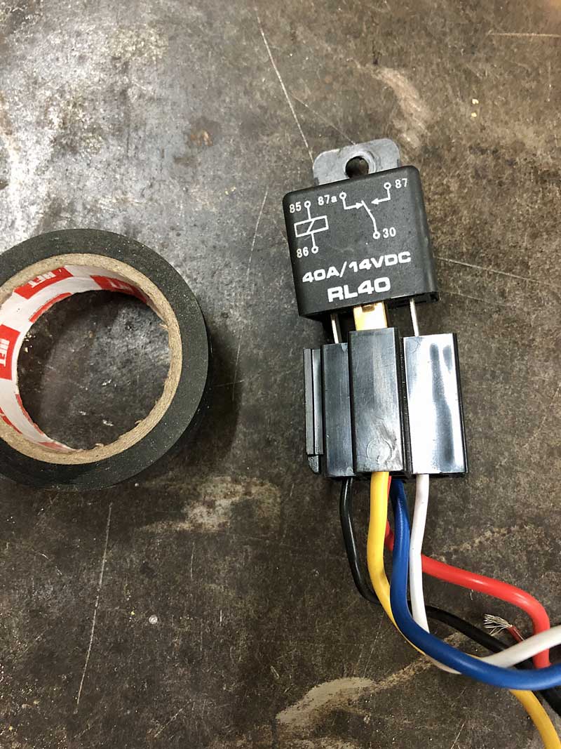
A short note from the Annexmaster about RELAYS Relays are a "thing" - that helps turn on or off electric devices. A switch does the same thing EXCEPT that the relay allows you to use a small amount of electricity and small wires to flip a switch far away. That saves you having to run a huge, long wire all the way to the switch and then back again. FOR EXAMPLE, think of a big air conditioner in your back yard. Huge wires, large fuses -- if you wanted a switch on your living room wall, you could run the huge wire all the way to the switch, and then back again to the back yard. OR you could put a relay in the back yard, and run tiny wires into the house. A relay (like the RL40 pictured below) uses a small amount of electricity to turn on or off a little magnet wherever the big wire is, that makes the big wires connect or not at the remote location. You use a tiny amount of electricity to operate the relay saving the larger electric load from having to go a longer distance. The foot switch in a Glassic is just a switch. Fat wire in from the battery, 2 fat wires out - one is connected for high beams, the other for low beams. Since the new switch will be on the dash, the relay will send the signal to flip those wires -- click down, low beams, click up high beams. |
 |
|
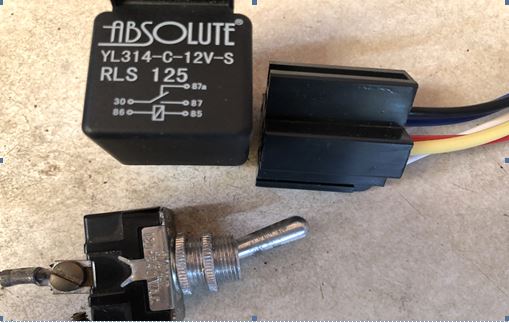
The items needed are
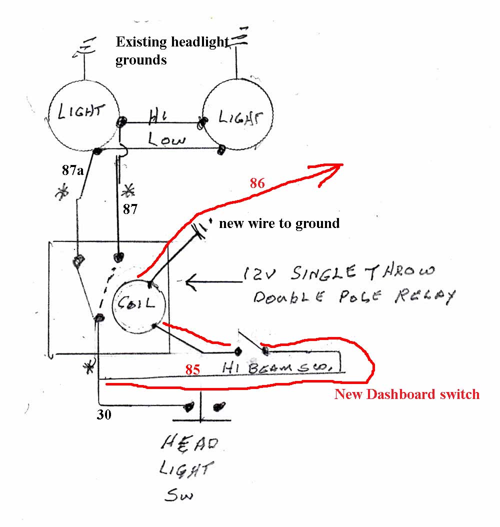
First you want to identify the wires going into the old foot switch. Power INTO that switch, which you will label #30, power OUT of that switch to the low beams which you can tag # 87a and then power OUT to the high beams, which will get a tag of # 87
To install, turn on the head lights on (low beam) and with a 12 volt tester check for voltage at the existing dimmer switch (you have to crawl under the car to do that) , there should be 2 hot wires (one is the power into the switch, and the other is out to the low beams of the lights), now put the head lights on high beam, now one of the two wires that were hot before will go out mark the wire that went out # 87a and the other wire that you had already tested will be # 30 or the power IN at this point the only wire that you have not checked yet should also be hot, mark it # 87 or power out to the high beams. Now disconnect the three wires from the existing dimmer switch and re-route to the relay location of your choice -- which in my case, is located under the dash?? in the engine compartment near ??? So, power IN #30 (This is power into the old foot switch, and will also be where the relay gets a little power when the headlight switch is on) Power OUT to low beams #87a Power OUT to the high beams #87
NOW to connect the toggle switch in the dashboard to the relay.
connections 85 and 86 are the two ends that will activate the relay. #85 is the power for that and 86 is the connection to ground. Your source of electricity to fire up the relay and make it work - is the same as the source that is running the headlights. On the harness, wire #30 will be connected to #30 on the relay, and also, a new length of wire that will run to the switch in the dashboard. Then another wire will run back to the relay from the switch. and be connected to 85. Then terminal 86 will require a ground of its own, so that when the toggle switch on the dash is UP, the power will go from the relay to the switch, back to the relay and then be grounded. Install a new wire from the relay to the switch and mark it # 85 (this is the skinny wire that is hooked in where connection 30 and wire 30 join at the wiring harness) install a new wire from the relay to a ground (-) # 86 This is the skinny wire whose job is only to complete the connection within the relay
So, you have terminals 85 and 86 as a new small separate circuit to make the relay switch the OTHER old foot switch circuit (the headlight high/low beam) go from power IN (30) to either 87 low beam or 87a high beam.
To operate Turn on the head lights, if the new dimmer switch is in the off position the head lights will be dim, turn ON the dimmer switch and it will be on high beam. Gerry says that the blue bright light indicator on the dash will continue to work as it did before. |